 ben's notes
Transforms
Introduction #
Transforms are functions $F$ that operate on points. They can be used to alter the position, rotation, and scale of objects.
Transforms are especially useful because coordinate systems are arbitrary- if needed, we can convert our objects into a convenient system, then convert it back when we’re done. For example, we may want to represent 3D objects in 2D space to model a scene.
Linear Transformations #
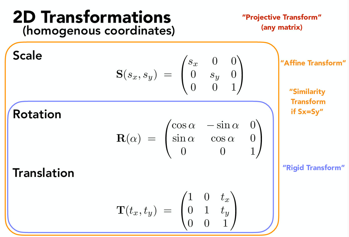
- A projective transform is any transform that can be represented as a matrix operation.
- An affine transform preserves parallel lines.
- A rigid transform preserves parallel lines and area. We can represent transformations as matrices to take advantage of linear algebra:
Rotation #
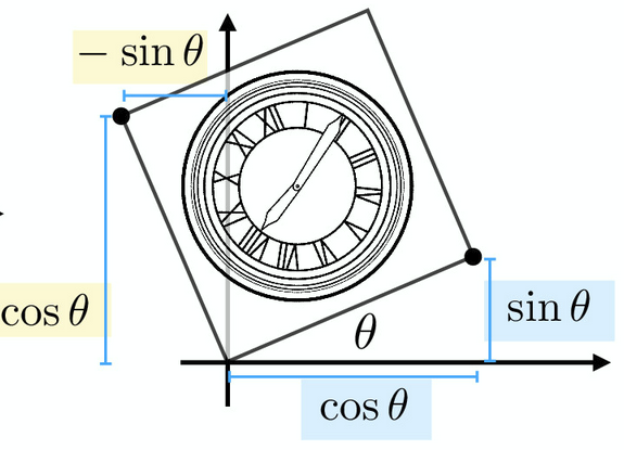
Rotating by the angle $\theta$ can be achived by using the transform matrix
$$ \begin{bmatrix} \cos \theta & -\sin \theta \\\ \sin \theta & \cos \theta\end{bmatrix} $$Rotation matrices are equivalent to orthonormal matrices since the inverse is equal to the transpose.
Translation (Homogenous Coordinates) #
With only this system, we can’t do translations (addition). As a solution, we can add a w-coordinate as follows: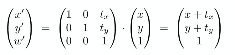
The w-coordinate is $0$ for vectors, and $1$ for points.
- Adding two vectors together results in a vector (value 0)
- Subtracting two points results in a vector (value 0)
- Adding a point and a vector results in a point (value 1)
- Adding two points is an undefined operation
The homogenous part of this system refers to the fact that the $w$ coordinate is always either $1$ or $0$. If it’s not, then we need to re-scale the result vector by dividing it by the value of $w$. The physical representation of this is distance: if something is translated to be far away, it should appear smaller.
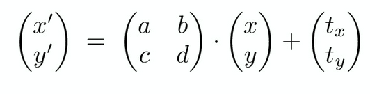
Homogenous translations are equivalent to an affine map:
Composite Transforms #
When combining multiple simple transformations, the order matters. For example, translating then rotating will result in a rotation about the origin with respect to the new position, whereas rotating then translating will rotate the object as expected.
A sequence of transformations can be represented as matrix multiplication. This allows us to easily represent complex transformations.
Here are some examples:
- Rotating about a given point $c$: $M_c = T(c) \cdot R(\alpha) \cdot T(-c))$
- Translate $c$ to origin
- Perform rotation
- Translate object back to point $c$
- Performing shears: $M_c = R(\alpha) \cdot S(1,k) \cdot R(-\alpha)$
- Rotate to shear axis
- Perform a single-axis scale
- Rotate back
SVD Property: Any matrix $A$ can be decomposed into $A = QSR^T$, where $Q,R$ are orthonormal and $S$ is diagonal. In other words, any linear transformation can be represented as a rotation, then a scale, then another rotation.
Coordinate Transform #
If we want to convert from one coordinate system to another, we can use the following transformation:
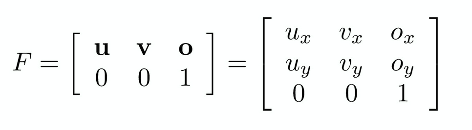 where $u$ is the new x-axis vector, $v$ is the new y-axis vector, and $o$ is the new origin.
We can interpret transformations as changing the coordinate system, rather than the object, when using this perspective.
3D Transforms #
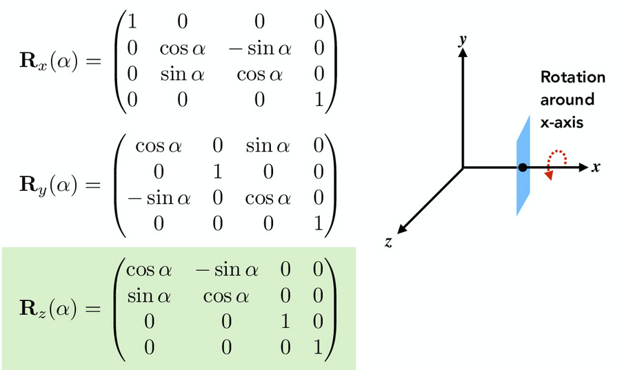
Operating in 3D is exactly the same as 2D, except we add an extra $z$ dimension. As an example, here’s how 3D rotations about each of the three axes look:
Reflections #
Reflecting over x-axis:
$$ \begin{bmatrix} 1 &0 \\\ 0 & -1 \end{bmatrix} $$Reflecting over y-axis:
$$ \begin{bmatrix} -1 &0 \\\ 0 & 1 \end{bmatrix} $$Reflecting about the line $y=x:$
$$ \begin{bmatrix} 0 & 1 \\\ 1 & 0 \end{bmatrix} $$Rotation Representations #
Euler Angles #
Euler angle property: All rotations can be decomposed into a multiplication of rotations about individual axes. (This is equivalent to roll, pitch, yaw). A list of three Euler angles is not a vector.
$$R_{xyz}(\alpha, \beta, \gamma) = R_x(\alpha) R_y(\beta) R_z (\gamma)$$This is nice, but has some problems:
- Gimbal lock: Rotations use absolute axes, so it’s hard to compute compound rotations. (If the orientation of the object changes, rotating about the ’new’ coordinate system is difficult.)
- Lack of uniqueness: There are an infinite number of ways to represent a particular orientation of an object in space.
Rotating about an Arbitrary Axis (Rodrigues Formula) #
If we want to rotate by angle $\alpha$ about an axis $n$, use this formula:

Essentially, this formula works by setting $n$ as an axis in a new coordinate system, then picking two arbitrary axes for the other two dimensions.
Exponential Maps #
We can represent any rotation by mapping it onto a sphere with radius $\pi$. This is equivalent to finding a matrix exponent:
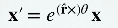
Using Euler’s identity and a power series expansion, we can evaluate the following:
 This representation solves many of the problems of Euler angles, namely that it allows for a nearly unique/1-1 mapping with no gimbal lock.
Hierarchical Transforms #
If we have many objects that are connected to each other (like a human body model), we can place the objects in a hierarchy such that the transforms of child objects are affected by transforms done to parent objects.
View Transforms #
If we have a 3D object but want to render it onto a 2D scene, we will need to perform transformations to preserve the perspective.
Assume these standard camera coordinates:
- The camera is located at the origin $e$, and is looking towards the negative z-axis (also known as $v$, the view direction).
- The y-axis represents the vertical vector (also known as $u$, or the up vector)
- The x-axis is orthogonal to the other two axes (the cross product $u \times v$).
Using the previously covered coordinate transform, we can convert any coordinate in the world space into the camera space:

Perspective View Transforms #
Simply getting the camera transform and deleting the $z$ axis will create a 2D image, but this image will not preserve perspective (the relative sizes of objects that are different distances away from the camera).
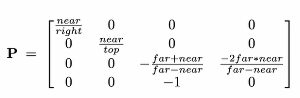
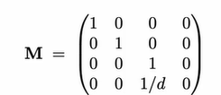
The following projection matrix models perspective by making $x, y$ a function of $z$:
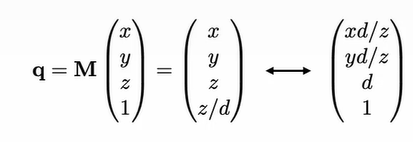
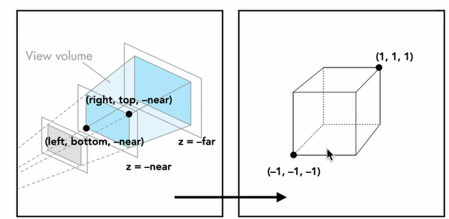
To specify camera perspective, we can use the concept of field of view to define a view volume. Rather than creating an image of the whole world, we only need to render objects within the view volume.
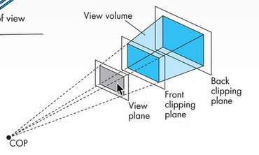 The front clipping plane blocks objects behind the camera from being processed. (It can also be in front of the camera to represent a 4th wall in a movie set.) The back clipping plane prevents an infinite amount of objects from being rendered (most objects very far away are barely visible anyways).
To make this view volume nicer to work with, we can transform the camera coordinates into Normalized Device Coordinates (NDC), which are mapped over a cube.