 ben's notes
Hardware Design
Synchronous Digital Systems #
Synchronous: there is a fixed global clock that determines the rate at which everything runs.
- Asynchronous systems are insanely difficult to debug so we don’t use them (yet).
Digital: made up of discrete 1’s and 0’s (unlike analog systems, which are a range).
- High voltage is 1 (true, asserted), low voltage is 0 (false, unasserted).
Synchronous Digital Systems consist of two basic types of circuits:
- Combinational Logic (CL) circuits have an output as a function only of its inputs, not the history of its execution. For example, an adder is a CL circuit.
- CL circuits don’t support feedback loops (for loops, etc). because they depend on the state of the program. All feedback must go to an intermediate register.
- Sequential Logic (SL) circuits store information (e.g. memory and registers).
Here’s a model for synchronous systems:
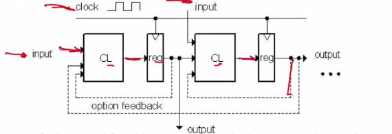
- A collection of combinational logic blocks separated by registers.
- Optionally, registers send feedback to their respective CL blocks.
- A clock (steady square wave, also known as CLK) synchronizes the system.
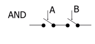
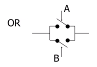
Switches #
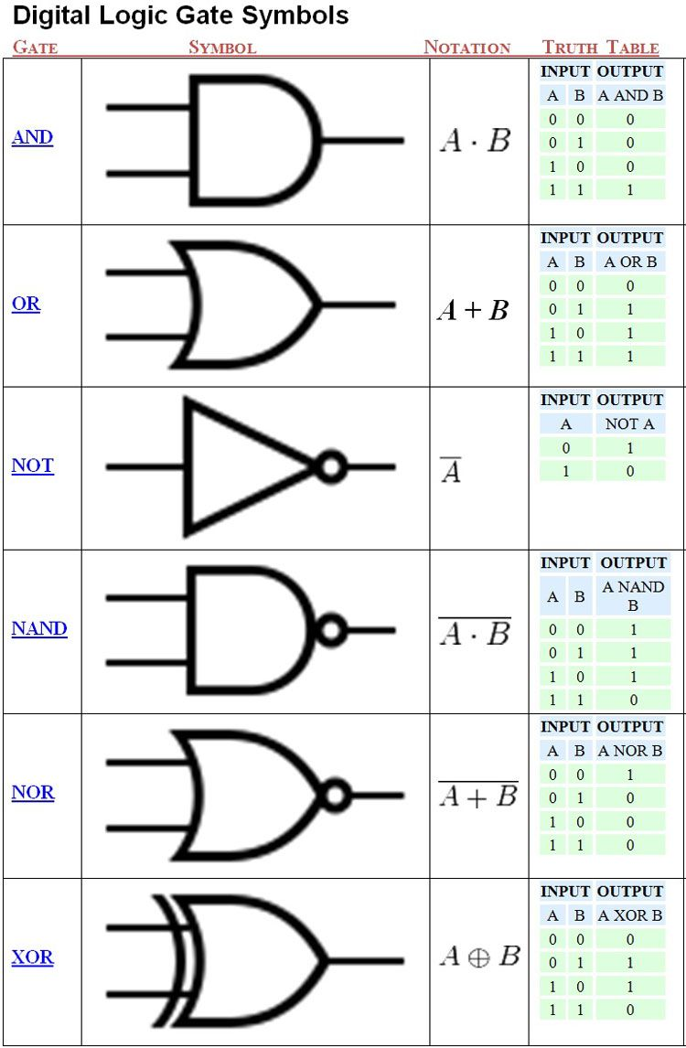
All digital circuits are made up of a bunch of switches (transistors). We can use these to make basic logic gates:
Transistors #
Transistors have a high voltage ($V_{DD}$) which represents 1, and a low voltage (ground) which represents 0. In order to reduce noise, we can set a midpoint voltage as a threshold
Modern digital systems are designed in CMOS (complementary metal-oxide on semiconductor) transistors, which are a combination of PMOS and NMOS (MOSFETs, or field effect transistors).
Transistors have 3 components: a source, drain, and gate:
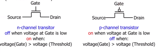
NMOS turns on when a voltage is applied to gate; POMS turns off when a voltage is applied to gate. The circle symbol on the PMOS is ‘NOT’ (complement).
For CMOS, we use complementary pairs of PMOS and NMOS because N-type transistors pass strong 0 signals, whereas P-type transistors pass strong 1 signals. So we can guarantee that either $V_{DD}$ or Ground get propagated, but they are never connected to each other.
CMOS works best with NAND, NOT and NOR gates.
Boolean Algebra #
Represent boolean operations with common symbols:
- for OR
- $\cdot$ for AND
- $\bar{A}$ (hat) for NOT
- $\oplus$ for XOR
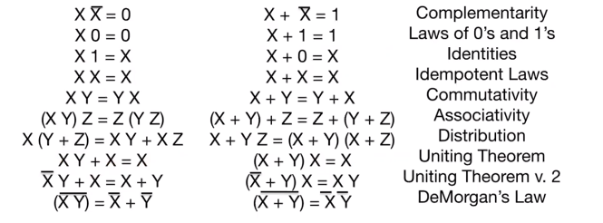
Laws of Boolean Algebra #
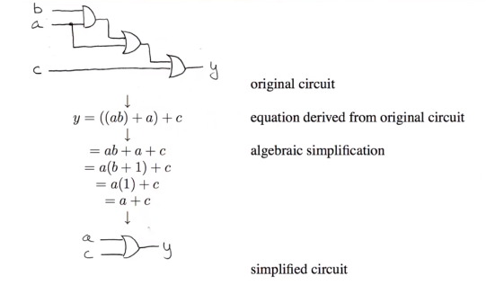
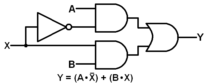
Representations of Combinational Logic #
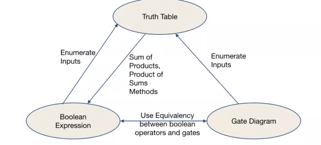
Converting between these three forms of representation can help us simplify circuits:
Registers #
How do computers store information?
The Flip Flop #
A Flip-Flop is an element that changes outputs from 1 to 0
A simple kind of Flip-Flop is the D Flip-Flop (D stands for data):
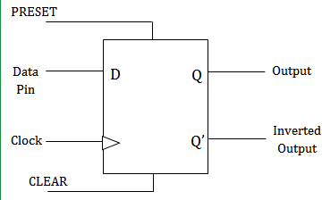
At certain clock intervals (‘clock edge’), it copies the input $D$ to the output $Q$. D-Flip-Flops have a:
- setup time (how much time does D need to be there before it’s copied),
- hold time (how much time is an output put out before it’s reset), and
- clock to Q time (how much time between the clock ticking and the output displaying)
Maximum Clock Frequency #
Recall that frequency = 1/period.
Since registers have setup and hold times, processing data isn’t instantaneous. We need to make sure that the process in a circuit is completed before an output is processed.
Period = CLK-to-Q Delay + CL Delay + Setup Time
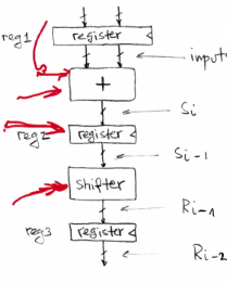
Adding more registers allows for a higher clock frequency, since operations can be done at the same time, like an assembly line:
Hold Time Violations #
If the clock-to-Q time and best case combinational delay are both less than the hold time, the data propagates but we don’t hold it long enough in the flip flop.
In order to solve this issue, we need to add delay on to the best case path (e.g. with an inverter).
On the opposite end, a critical path is the longest (worst case) delay of propagation throughout a CL circuit.
State Machines #
A finite-state machine (FSM) is an abstract model that links states with transitions. They are very similar to Markov chains.

Types of State Machines #
A Mealy machine is one where the output is a function of both input and current state.
A Moore machine only depends on the current state.
Compared to Mealy machines, they require more states, and require more clock cycles to respond. However, they can be clocked at a higher rate.
Hardware Implementation #
Basic Building Blocks #
Data Multiplexer: Mux #
Given two n-length bits as input, selects one based on a particular condition and outputs that n-bit sequence.
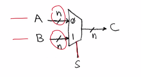
S is the selector bit: if s=0, then it’ll output A. Otherwise, it’ll output B.
In boolean algebra: $c = \bar{s}a + sb$.
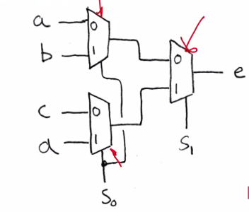
We can expand a multiplexer to build larger multiplexers (for example, a 4-1 mux, which takes in 4 inputs and outputs 1). This can be done by chaining some 1-bit muxes together:
Arithmetic Logic Unit: ALU #
Most processors contain a fundamental logic block that performs basic arithmetic and logical operations: the ALU.
The ALU supports operations like addition, subtraction, left and right shifts, etc.