 ben's notes
Operating Systems
Introduction #
The OS is a large piece of software that acts as a layer between hardware and user programs. Some of its functions include: (For a much deeper treatment of every topic on this page — processes, threads, scheduling, virtual memory, file systems — see the CS 162 notes, starting with Chapter 1 OS Basics.)
- Loading on boot
- Managing IO devices via drivers
- Starts services for managing filesystems, network, etc.
- Loads, runs, and manages multiple programs and resources simultaneously and safely
- Mediates interactions between running programs, processes, and hardware
- Makes interaction with the outside world uniform, even if the underlying hardware may be different
Safe Sharing of Resources #
The OS gives each process isolation: even though multiple processes might need to share hardware, each process gets its own view that it owns the whole machine:
- Processes can’t see other processes’ computations or resources.
- Each process has the illusion that it can access the entire address space.
To do this, we share time on the CPU (context switching) and space in memory (virtual memory). Hardware-wise, this is allowed by:
- Memory translation: a map from virtual to physical addresses. Programs all interface with virtual memory, which is represented as space in actual memory.
- Protection and privilege: splits the processor into multiple modes (i.e. user and supervisor). Certain commands can be run only by a supervisor process (such as the OS itself). This is implemented with control and status registers that are used to communicate requests with the hardware.
csrrw rd rs csrputs the old value of the specified registercsrand puts it intord. Ifrsis nonzero, it writes the value ofrsintocsr.
- Traps and interrupts: a method of going into supervisor mode on demand.
- An interrupt means that something happens from the outside world that needs to be addressed. (Example: key press, disk IO). Asynchronous to the current program and can be addressed “whenever it’s convenient”
- An exception means that something is done by the running program that results in unintended behavior. (For example, segfaults, illegal instructions, reading csr in user mode)
ECALLtriggers an exception to the higher privilege and is used to communicate with the operating system. (Used to ask the OS to perform some task with a higher privilege)EBREAKtriggers an exception with the current privilege.- Exceptions are synchronous and must be handled exactly on the instruction that causes the exception.
- Precise traps: the view that every instruction prior to the trapped one has completed, and no instruction after the trap has executed. This means that the handler can return from an interrupt by restoring registers to that state and jumping back to the interrupted instruction.
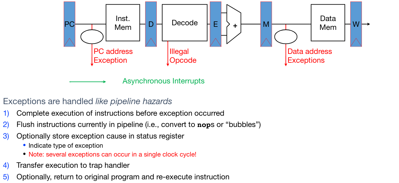
Hardware response to traps:
- Adjust privilege level if needed
- Disable interrupts (so the interrupt doesn’t get interrupted)
- Write the old program counter to the
sepcCSR- If exception, write the PC at the exception.
- If interrupt, write the first non-executed instruction.
- Write the reason into the
scauseCSR - Set the PC to the value in the
stvecCSR (address of trap handler) - Run trap handler function
- Save all registers into
sscratchCSR - Run logic corresponding to exception or interrupt response
- Restore all registers
- Return to original point of execution (
SRETinstruction)
- Save all registers into
Device IO #
We can read inputs from devices like a mouse, etc. by using polling: before executing an instruction, check the value in a device register and act based on that value.
Polling can be time and CPU consuming. Another strategy is to use interrupts to proactively notify the processor when something has occurred. This allows the CPU to not waste cycles polling when no data is present. However, each individual interrupt is expensive.
As a compromise, we can start each burst of data with an interrupt, then switch to polling once data is starting to arrive.
Modern device IO #
In modern devices, USB actually doesn’t support interrupts, so everything is done during polling.
Polling usually takes a large overhead (since all caches must be cleared when switching to and from a user program). To resolve this, modern devices have a timer interrupt that occurs every ~10ms, so simply adding the device request into the standard timer interrupt takes very little additional overhead.
Boot Sequence #
When the computer is booted, these steps need to be performed:
- BIOS/UEFI: Firmware that finds a storage device and loads the first sector
- Bootloader: Loads the OS kernel into memory and jump to it
- OS Boot: Initialize services, drivers, etc
- Init: Launch an input loop (terminal, desktop, etc) that then is used to launch child programs
Launching Applications #
Applications are known as processes. Each process has its own address space and threads of execution (sequences of code to run). Each process is isolated (don’t care about other processes) and run pseudo-simultaneously (switch between process quickly such that it is indistingishable to the user).
Applications are started by another process (such as the shell) using a syscall. This loads the executable file from the disk and loads instructions+data into memory, stack, and heap.
- Linux:
fork()andexecveto execute file command - RISC-V:
ecall
Virtual Memory #
Supervisor mode alone can’t fully isolate applications from each other, since applications could overwrite others in memory or access the same address at the same time.
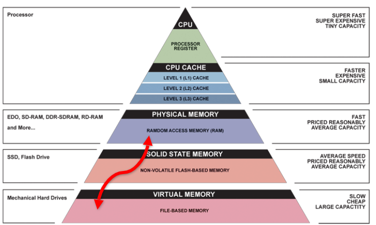
The solution is virtual memory. This has three uses:
- Add disks to hierarchy: connect RAM with solid state memory.
- Simplify memory for apps: provide a layer of abstraction for processes
- Protection between processes: have a layer of checks and controls to mediate access to memory and reject requests to memory that should not be accessible from a particular process. Malicious code shouldn’t be able to corrupt the rest of the computer.
Address Spaces #
An address space is a set of all possible memory addresses accessible by a process.
- Virtual address spaces are what the user program know about.
- Physical address spaces are hidden from user applications and map to actual locations in physical memory. The OS uses this to manage IO from processes.
Blocks vs. Pages #
Caches are usually divided into blocks, which are 32-128 bytes of memory.
On the other hand, virtual memory is divided into pages, which are larger at about 4-8KB. Pages can each be divided into smaller blocks, which are then divided into words and bytes.
Both blocks and pages (and bytes and words for that matter) are simply ways to represent continuous chunks of memory.
Address Translation and Page Tables #
We need to figure out a way to map virtual page numbers and offsets in the virtual address space into physical page numbers and offsets in physical address space.
In order to achieve this goal, we need to keep a page table that contains the physical address of each virtual page.
- Each process gets a unique, isolated page table.
- The page table can act like a cache that changes a pointer from slower to faster memory for frequently used data.
- The size of page tables are proportional to the size of the address space (too large to fit in registers). Therefore, they must also be stored in main memory.
Linear Page Table #
A simple type of page table is a linear page table, which is similar to an array that contains entries at indices. Each page table entry (PTE) contains:
- 1 bit, indicator for if the page exists
- Status bits for protection (read write execute)
- Either one of:
- Physical page number (PPN) for a page in memory
- Disk page number (DPN) for a page in disk
There is a special register, the Page Table Base Register (PTBR), that points to the beginning of the page table.
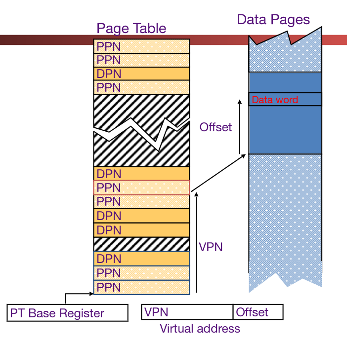
If a memory page isn’t actually in DRAM, then a page fault is raised. A page fault handler must then update the location by finding it in the disk and re-assign it to an unused DRAM page.
A major flaw of the linear page table is that it takes a lot of space to store information in this manner.
Hierarchical Page Table #
Rather than model the page table after an array, we can model it after a tree.
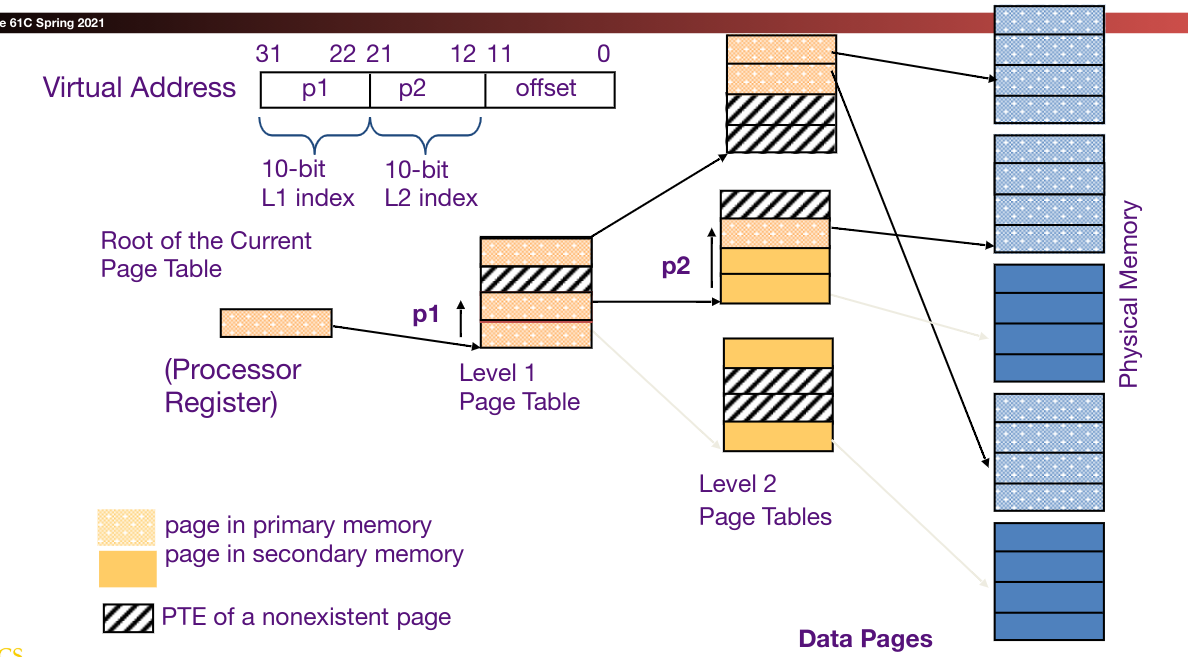
Each node in a sub-page table has a child for each entry in the page table. This takes advantage of the sparsity of virtual address spaces since we don’t have to store a large amount of empty pages.
Translation Lookaside Buffers (TLB) #
The TLB is basically a cache that stores some translations from PPN to DPN. This way, we can hopefully offload some expensive disk lookup operations to cached values in the TLB.
TLBs usually hold 32-128 entries with high associativity. They have a random or FIFO replacement policy.
The TLB Reach is the size of the largest possible range of virtual addresses in which we will always have a TLB hit.
TLB Reach = # of entries * Size of each entry * number of pages per entry
Here’s the updated pipeline to handle TLB:
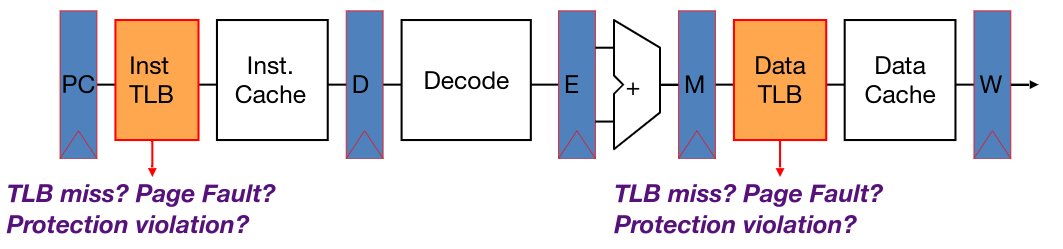
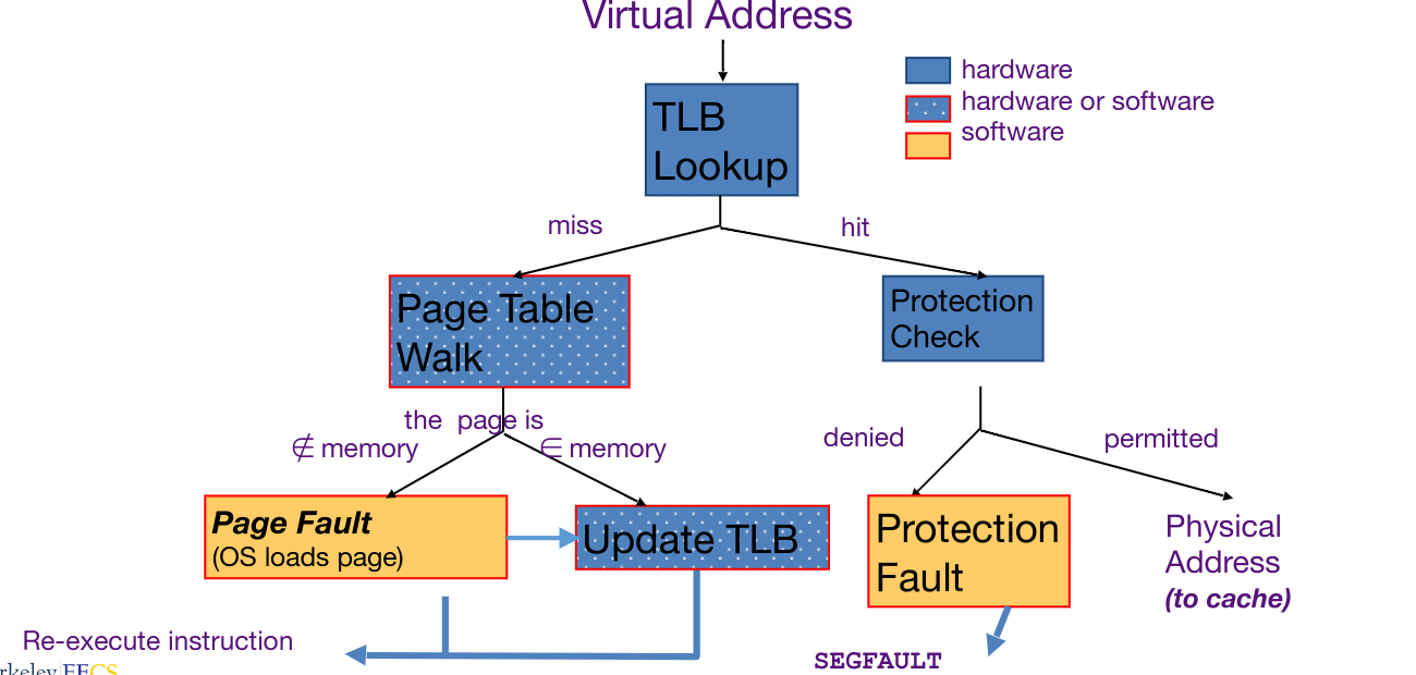
This pipeline can be implemented in two ways: hardware (x86) or software (MIPS). Hardware implementations are faster, but introduce extra complexity in the pipeline. Below is a diagram of possible operations that can be performed to map a virtual address to physical address.
I/O #
Devices are memory. By reading and writing to memory addresses, it is possible to send and retrieve information from devices just like for DRAM, etc.
- Device drivers run in the OS and provide a layer of abstraction for programs.
- All interactions with hardware is mediated by hardware (due to security and permissions)
- A memory bus controller acts as the interface between the CPU and DRAM.
IO is asynchronous. Devices don’t run with the same clock cycles as the CPU, so requests can occur at any time without coordination. We must handle this with either polling (periodically ask for data) or with interrupts (trap handling to jump control to handler).
Interrupt-Driven Handling #
- Highly responsive - data is handled right when it comes in.
- Efficient for low rates (since computer can handle other things), but inefficient for high rates (constantly switching contexts is very expensive; caches and pipeline get flushed every time)
- A common compromise is to interrupt by default, then poll when faster rates are needed
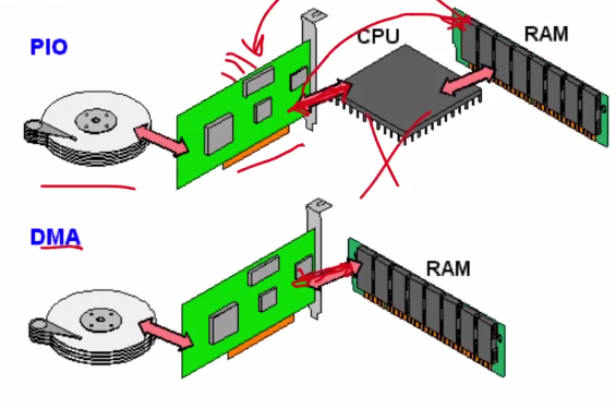
Programmed IO #
Programmed IO is when devices are directly mapped to registers in the CPU. While simple, this is not ideal because:
- The CPU has to execute all data transfers.
- Device speeds are much slower than the CPU clock rate in most cases.
- IO computations can be executed by a simpler processor.
DMA #
Direct Memory Access (DMA) is another interface scheme where IO devices directly read and write to main memory, rather than needing to go through the CPU first.
DMA requires a new piece of hardware, the DMA engine, which contains CSR registers. The CPU writes parameters to these CSR registers (memory address, # bytes, device ID, read vs. write, amount to transfer, etc.) and will ask the DMA engine to perform the operation on its behalf.
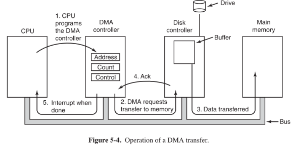
The DMA pathway for incoming data:
- First, the DMA receives an interrupt from the device.
- The CPU receives the interrupt and instructs the DMA engine to begin the transfer. (The interrupt can be replaced by a dedicated section in memory that the DMA engine just immediately writes to without asking.)
- The DMA engine then handles the transfer while the CPU executes other instructions.
- When the transfer is complete, the DMA engine interrupts the CPU again.
The DMA pathway for outgoing data:
- The CPU first confirms that the external devices is ready.
- The CPU then begins the transfer by instructing the DMA engine to write data at a particular address.
- The DMA engine handles the transfer while the CPU executes other instructions.
- The DMA engine interrupts the CPU to notify of succssful transfer.
DMA Considerations:
- If placed between L1 and CPU, there will be cache coherence but the CPU cache will be full of transferred data.
- If placed between the last-level cache and main memory, then there would need to be explicit coherence management, but it won’t mess with the caches.
- DMA can also be treated like another node in a multiprocessor, which standard cache coherence mechanisms can work upon.
- To arbitrate memory access between CPU and DMA engine, we have a few options:
- Burst mode: when DMA engine needs memory access, it will write the entire data block and restrict access from the CPU until it is done.
- Cycle Stealing Mode: DMA engine shares traffic with the CPU, writing a bunch of small chunks over time while the CPU still writes.
- Transparent mode: CPU has priority; the DMA engine only writes when the CPU is not using the system bus.
- In order to perform IO for an unprivileged process (like a user program), we can map DMA regions into the program’s virtual memory space. So once things are set up, IO operations don’t need to go through the OS.
IO Devices #
Magnetic Disk #
- Two types: HDD’s, floppy disks
- Non-volatile (retains value without power)
- Stores memory by magnetizing ferite material on rotating disk
- Large, inexpensive, slow
- Disk access time = seek time + rotation time + transfer time + controller overhead
- Seek time = time it takes for read-write head to move to proper place
- Rotation time = time it takes for the correct sector of disk to fall under the head
- Transfer time = time taken to read entire sector (and any gaps)
- Controller overhead = time it takes for disk to react to commands
Networking IO #
A quick history of the internet:
- In the 1960s, universities had their own networks…
- In 1963-1969, the question arised of the feasibility of creating a “network of networks”, and thus ARPA was created to connect multiple universities together.
- In 1989, HTTP was proposed by Berners-Lee.
Shared vs Switch Based Networks #
A shared network is one such that only one device can talk at a time. An example is a wireless home network.
Switched networks have pairs of devices talking to each other simultaneously. This creates an issue of access:
- In ethernet, a “listen and send” model is used: if another device is talking, wait. If no devices are talking, immediately send data. If two devices request at the same time, then wait a random amount of time before attempting again.
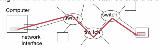
- For the internet, we have a network of links connecting switches and routers to each other. To send and request data, we need to be able to name the destination.
Sending and Receiving Data #
- Application copies data to the OS buffer.
- The OS calculates the checksum and starts a timer.
- The OS sends a DMA request to the network interface.
Packets of data are sent at a time. If the checksum is correct, they are received; if not, they disappear.
The OSI 7 Layer Network Model #
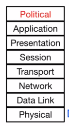
- Physical: The wires and wireless connections.
- Data link: Ethernet.
- Network layer: IP (how we communicate between networks)
- Transport layer: TCP/UDP (provides additional functionality)
- Session and presentation layers: unused.
- Application layer: browsers and servers that get run by users
Protocol Family Concept #
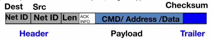
A protocol is a packet structure and a set of control commands to manage communication.
Protocol families (suites) are sets of cooperating protocols.
- As an analogy, we can think of the process of sending a letter/package. This needs to go through multiple people and delivery firms.
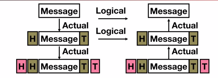
- Each individual layer only needs to care about the layer directly above or below: everything else is handled by the network. (For example, we as the sender of a package don’t need to manage how FedEx sorts and transports the package. It’s all abstracted away.)
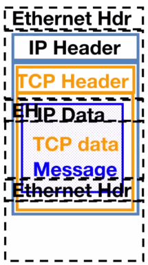
- More concretely, we take a message and continually wrap it with more information per layer. This process is known as encapsulation.
TCP #
TCP/IP (Transmission Control Protocol, Internet Protocol) is the basis of the internet.
- IP makes the best effort to deliver, but packets can be corrupted or lost.
- TCP guarantees reliable, in-order delivery of a bytestream. As such, programs read and write strings of bytes rather than needing to handle packets.
- TCP is used whenever reliable communication is required.
- TCP is connection-based (syn → syn/ack → ack) and involves a 3-way handshake. All data must be acknowledged. (syn = synchronize, ack = acknowledge)
UDP #
UDP (User Datagram Protocol) is, as named, datagram-based.
- UDP is out of order and unreliable. Datagrams can arrive in any order.
- UDP is used for realtime communications since it eliminates the need for multiple handshakes and pauses.
GPIO #
We already have high-performance IO (DMA controller) and flexible IO (USB).
GPIO is a way to handle human-scale IO (on the matter of seconds or hours). GPIO consists of physical pins attached to the CPU, that can be read from and written to.
In Linux, GPIO pins correspond to files. As such, GPIO gives very simple interfaces and programming models, at the expense of being very inefficient. However, we don’t care if we waste millions of CPU cycles, since they wouldn’t be detectable by humans anyways.