 ben's notes
RISC-V Processor Datapath
The State #
Each instruction reads and updates the state during execution. The state includes:
- Registers (x0 to x31)
- Find rs1 and rs2
- Write to rd (destination)
- Writes to x0 are ignored
- Program counter (PC)
- Holds address of current instruction
- Memory (MEM)
- Holds both instructions and data in a 32-bit byte addressed memory space
- Separate memory for instructions (IMEM) and data (DMEM)
- Instructions are read from IMEM, load and store instructions access DMEM
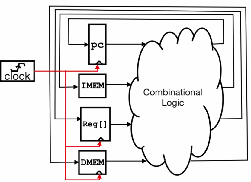
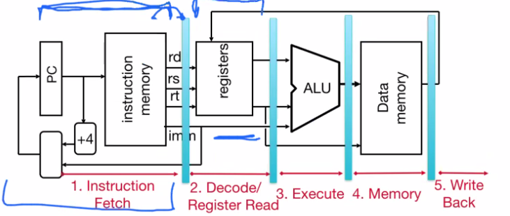
An abstract representation of a one-instruction-per-cycle RISC-V machine
- Current state outputs become inputs to combinational logic. The outputs from here become the value of the state before the next clock edge.
- At the rising clock edge, all state elements are updated with combinational logic outputs.
- Memory is asynchronous read, but synchronous write.
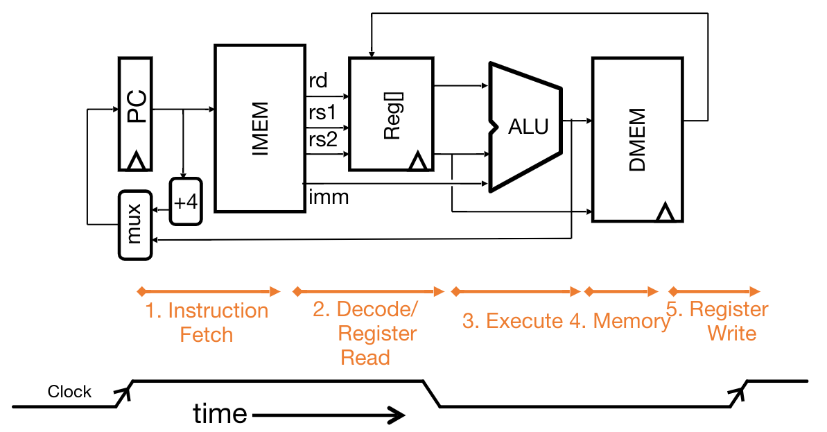
Basic Phases of Instruction Execution #
Fetch, Decode, Execute, Memory, Write: one clock cycle
Example: the add instruction #
add rd, rs1, rs2 decomposes into the following operations:
Reg[rd] = Reg[rs1] + Reg[rs2]PC = PC + 4
The datapath (set of hardware) required to execute the instruction is as follows:

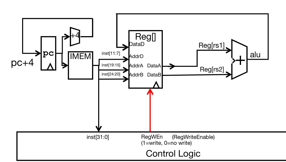
Other R-type instructions are processed very similarly, except the control logic must select a different operation for the ALU to carry out depending on the function code.
Immediates (I-instructions) #
Here’s the instruction for addi:

The control logic must be modified to allow for processing of the immediate input:
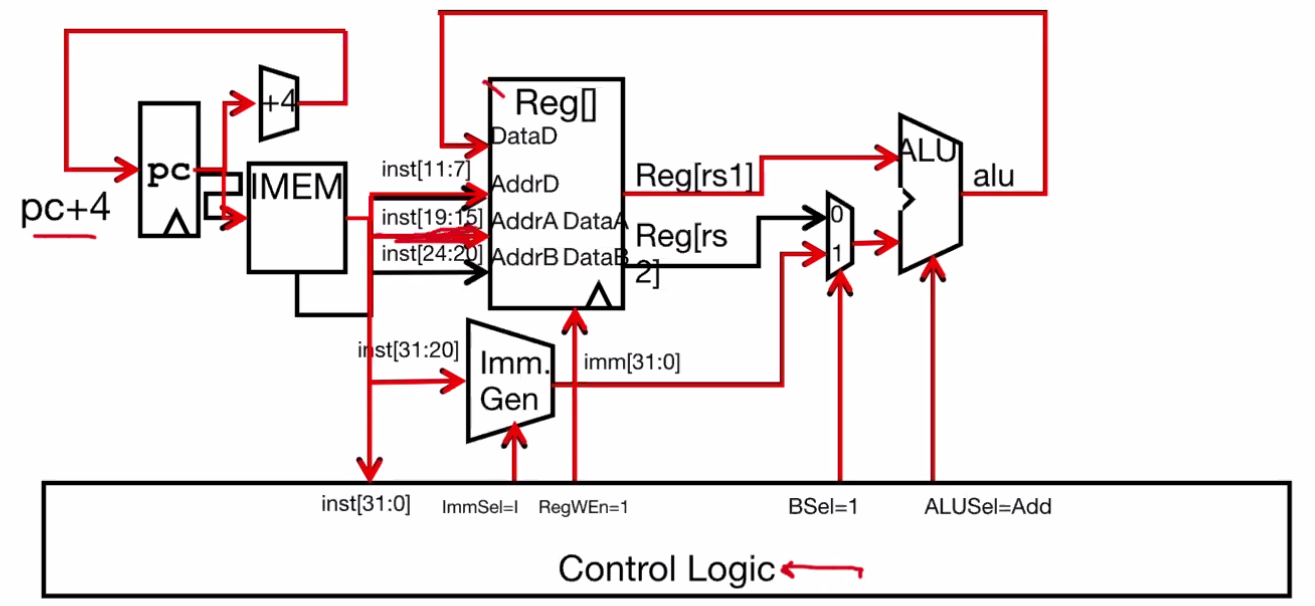
Since there’s only 1 register for input (rs1), the second register input must be replaced with an immediate. We can control this logic flow using multiplexers (e.g. BSel).
Summary #
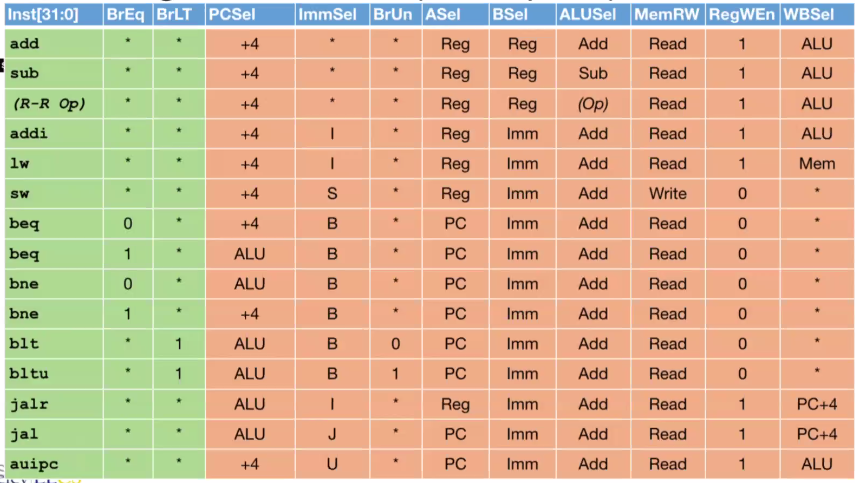
Control Block Design #
- PCSel = PC selector
- ImmSel = immediate selector
- BrUn = unsigned or not
- ASel = program counter vs A register
- BSel = immediate vs B register
- ALUSel = tell ALU what operation to do
- MemRW = read vs write memory
- RegWEn = write into register vs don’t write
- WBSel = writeback mux selector
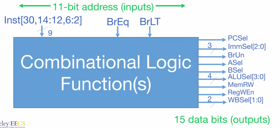
In order to implement the control block, we can either store the logic into a hard-coded truth table (ROM), or enumerate the logic into gates. Doing the former is simpler to understand and implement, doing the latter is more efficient.
ROM implementation #
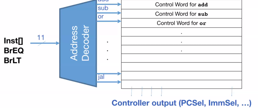
If we want to implement the logic using ROM, we use an address decoder to map particular inputs to outputs. However, this takes a while to run:
The critical path is lw, since loading requires all the steps listed above. This means that most blocks don’t do a whole lot, because some instructions (e.g. write to memory) don’t run for most instructions.
We want to improve performance- but what exactly is performance??
- Latency: program execution time
- Throughput: number of tasks handled per unit time
- Energy per task: how many tasks can be completed with a certain amount of power
The Iron Law of processor performance #
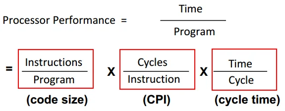
Instructions per Program #
The number of instructions needed is determined by:
- The task that needs to be done,
- The algorithm used to carry out that task (and its runtime complexity),
- The programming language,
- The compiler,
- THe instruction set,
- The input.
Average Clock Cycles per Instruction (CPI) #
This is determined by:
- The instruction set (CISC vs RISC),
- The microarchitecture (processor implementation),
- Number of cores
Time per Cycle
- 1/frequency
- Processor microarchitecture
- Technology (process node)
- Clock speed
The Iron Law of Energy #
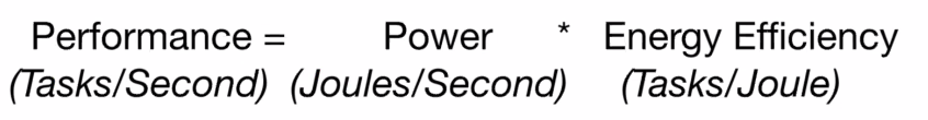
We always want things to be energy efficient, not power efficient.
Pipelining #
Here’s an example of how pipelining increases the throughput without needing to decrease the amount of time (latency) spent per student in a college education:
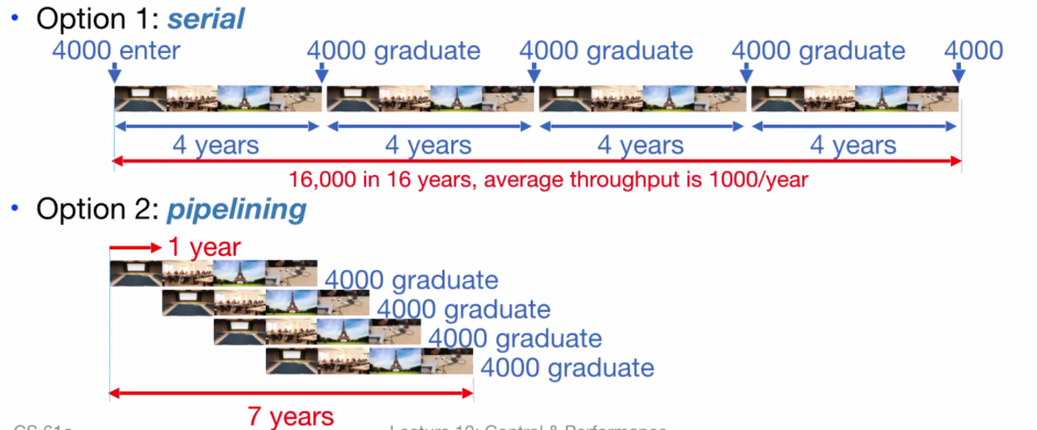
To reiterate, pipelining is bad for latency, but makes throughput better.
Pipelining in RISC-V #
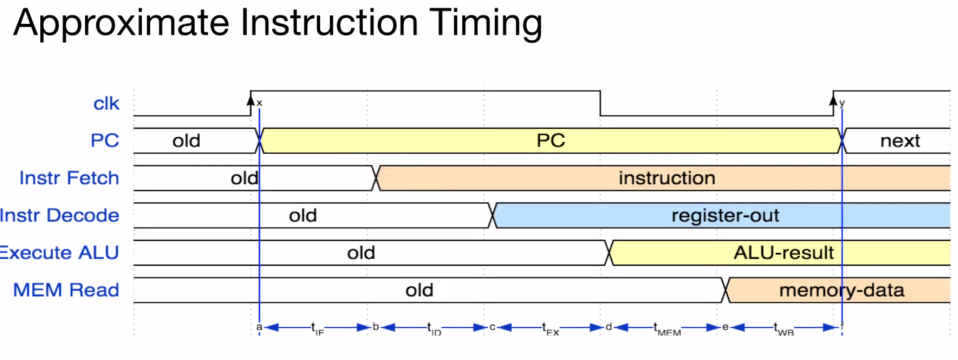
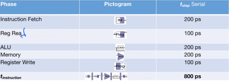
In RISC-V, there are 5 main steps (instruction fetch, register read, ALU, memory, register write). The $t_{step}$ column is a very rough approximation of the time it usually takes each step to process.
We can see that in this example, a single instruction takes 800ps.
If we want to pipeline this process, we can insert a register in between each step and use a clock cycle to process a single part at a time.
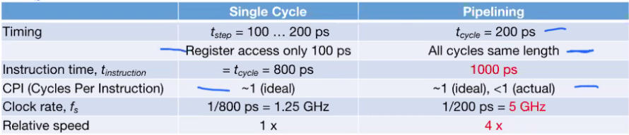
By doing so, we are using 5 clock cycles per instruction rather than 1, but the clock period becomes far faster (the slowest step, 200ps).
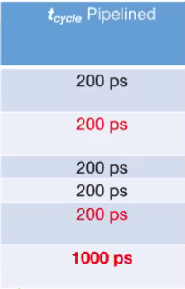
This makes our latency worse (1000ps from 800), but our clock rate is now 5 times the original. Doing the math shows that the relative speed using pipelining is actually 4x faster!
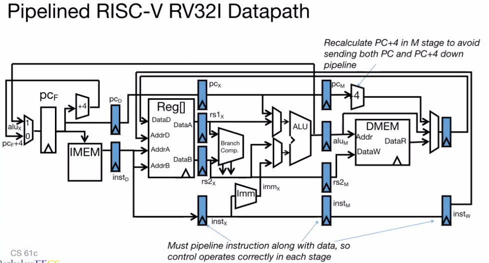
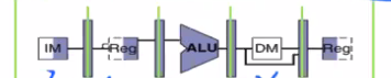
Here’s how the full datapath looks like, now with registers:
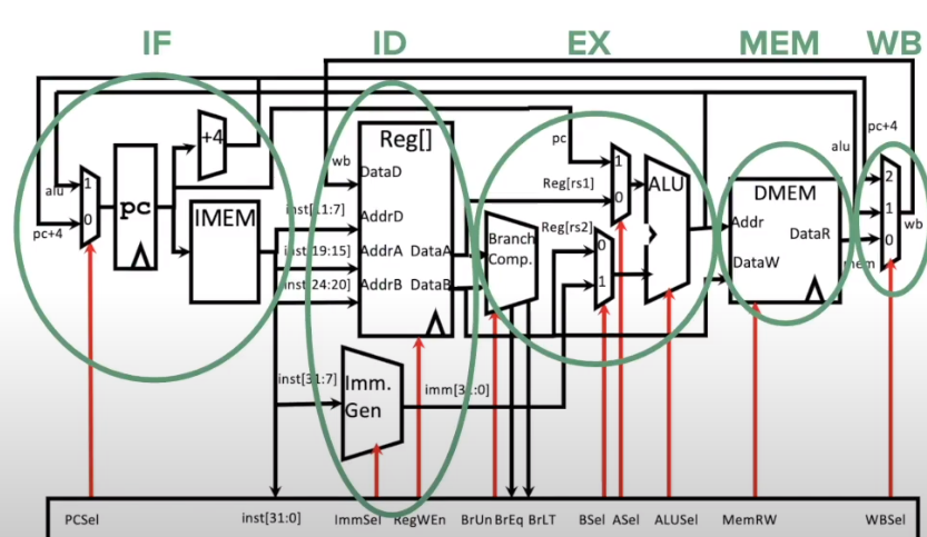
Here is a chart showing some common instructions and the stages in the datapath they require:
IF: Instruction Fetch - looks into instruction memory (IMEM) and returns the machine code representation of the instruction at the program counter (PC)
ID: Instruction Decode - uses machine code instructions to figure out what registers we are reading or writing to. Also handles immediates and sign extension if necessary
EX: Execute - determines if a branch needs to be taken, OR computes logical instructions in the ALU
MEM: Data Memory - if we have a load or store instruction, then we will read from or write to our memory (DMEM)
WB: Writeback - determines the value that will be written back to the destination register
Instructions don’t always use every step in the path. For example, the add instruction does not need to write to memory, so it skips the MEM stage.
Pipelining Hazards #
A hazard is a situation that prevents starting the next instruction in the next clock cycle.
Structural hazard: A required resource is busy (e.g. needed in multiple stages). This can be resolved by modifying the datapath.
- This can be resolved by either making instructions take turns to use a particular resource, or simply duplicate the hardware so that each instruction can use its own copy.
- For devices such as registers that might have multiple reads and writes occurring simultaneously, we can resolve structural hazard by having multiple independent ports such that a single device can support simultaneous read and write operations.
- Overall, this is primarily a hardware issue.
Data hazard: There is a dependency between instructions (i.e. an instruction requires the result from an instruction that has not yet completed).
- We can resolve this by introducing a register access policy: since registers are fast compared to other operations, we can use the first half of the cycle to write to registers, and the second half of the cycle to read to registers. That way we can access data that has been written in the same cycle.
- We could try solving this by stalling: waiting for the previous needed instruction to complete before resuming the pipeline. However, this makes the program run more slowly and breaks the abstraction between the hardware and software.
- We could also use forwarding (aka bypassing): the moment the instruction is processed in a sub-step (e.g. written to a register in the 2nd step), we are able to pass that result directly to the next instruction in the pipeline to use the previous instruction’s register value as one of the ALU inputs. This saves some cycles of waiting time over stalling. This doesn’t always work, however; it is sometimes unavoidable to stall.
- If this happens, we can store a value into a load delay slot. If an instruction uses the load delay slot, then it indicates for the hardware to stall for one cycle. This is equivalent to inserting a
nopinto the slot. One way to make things more efficient is to put an unrelated instruction into the slot.
- If this happens, we can store a value into a load delay slot. If an instruction uses the load delay slot, then it indicates for the hardware to stall for one cycle. This is equivalent to inserting a
Control hazard: The flow of execution requires the result of an instruction that has not yet completed.